Chapter 18 Topo Topographical Display
It is sometimes useful to organize fixture selection in a graphical manner instead of numerical lists. In Vibe this is referred to as the TOPO (Topographical) map display. Other console may refer to this feature as “Layouts”, “Magic Sheets”, or “Rig” Schematics”.
The following is covered in this chapter:
- 18.1. Creating a Topo View
- 18.2. Topo Menu
- 18.3. Creating a Topo
- 18.4. Adding fixtures
- 18.5. Adding Pixel Maps
- 18.6. Adding Softkeys
- 18.7. Adding Text Elements
- 18.8. Adding Background Image
18.1 Creating a Topo View
When starting a new show any Topo views stored in Layouts will be empty until the system is patched and fixtures are assigned to a Topo. If no layout contains a Topo view, a Topo view must be added to a blank page. Virtually unlimited Topos may be created and displayed in a Topo view. Fixtures may be shared by Topos.

Topo View in {LIVE} mode displaying the “Movers” Topo
To add a Topo view to a page:
Tap {Vibe} on the monitor that will display the Topo - Vibe menu will open.
Tap {Pages} - Page display will open.
Add a blank page from either the {Programming} or {Playback} work space templates - A blank workspace will open.
On the screen with the blank workspace, open the {Vibe} menu again and select}
⟶ {Display Objects}
⟶ {Topo View} - A blank Topo view will appear on the workspace.
Size and drag the Topo display as required then tap {unlock/lock} icon to lock the Topo from further adjustment - Topo display is now ready to add fixtures to.
Select the desired Topo number, and give the Topo a unique name.
Enter the size of the Stage surface. The stage dimensions may be in be in Imperial or Metric. This default is set in the System Settings pop-up.
Select the stage point of view. The default is Top view.
Tap
 or press [ENTER] - This closes the pop-up, enters Topo {Edit} mode, and the grid will be displayed.
18.2 Topo Menu
The Topo Menu is a hierarchical menu that provides the tools for creating and editing Topos. If the {LIVE} mode is enabled the Topo is in active mode and can be used to select objects and trigger elements. To Edit objects, the {EDIT} mode button in the bottom right area of the Topo view must be enabled. The menu and control bar frames will switch from green to red color.
The root menu provides the following sub-menus:
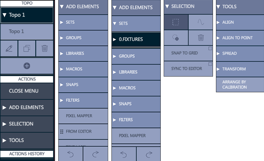
{Add Elements} - Accesses the following objects:
{Sets} Opens the filter of all available fixture sets: Global fixture, Channels, Spots, Matrix, Servers, and users created sets.
{Groups} Opens the filter of all available groups.
{Libraries} Opens the filter of all available libraries (Intensity, Position, Color, …).
{Macros} Opens the filter of all available macros.
{Snaps} Opens the filter of all available snaps.
{Filters} Opens the filter of all available filters.
{Pixel Mapper} Adds a User definable Pixel Map matrix to the Topo surface. Refer to chapter 19.5. Adding Pixel Maps
{From Editor} Allows to Drag&Drop on the Topo the elements that are selected in Vibe’s editor.
{Text Label} Opens a popup to create a customizable text label.
{Line} Adds a customizable line to the Topo.
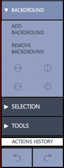
{Background} Adds a customizable background to the Topo.
{Selection} – Accesses the selection options
Rectangle: Select by creating a rectangular lasso, dragging from left to right or right to left to create a rectangle around or through the objects.
Lasso: Select by creating a free-form path, dragging through objects.
De-select all.
Delete selected (only valid in Edit Mode).
Snap to Grid - Fixtures and object will snap to the nearest grid node.
Sync to Editor - In edit mode, fixtures can be selected using the embedded keypad.
Selection may be used in Live mode or Edit mode.
All types of selection must start outside of the fixture icons.
{Tools} - Accesses the smart adjustment options
{Align}: Aligns the selected elements horizontally to the left, center or right, and vertically to the top, middle or bottom. The alignment can also be set on a circular or a square shape and between two points it is possible to adjust the element location on the shape, the radius and the ending point.
{Align to Point}: A base point must be specified on the Topo surface as a starting reference. The options are the same as Align except there is no point to point.
{Spread} (Fan): Spreads the selected elements horizontally from the left, center or right, and vertically from the top, middle or bottom. When Spread is selected, a virtual modifier wheel will appear.
{Transform} - Modifies size and rotation of the objects to scale and rotate and to rotate of 45 degrees clockwise or counterclockwise. The last icon is to resets the transform options.
{Arrange by Calibration} - When tapped, selected Topo fixtures get their positions from the XYZ calibration. See chapter 19. XYZ Fixture Calibration.
18.3 Creating a Topo
To create a new Topo:
Navigate to a Topo view
- Tap the {
 } key in the Topo Menu at the right hand side of the Topo view display - The “Create New Topo” pop-up will appear
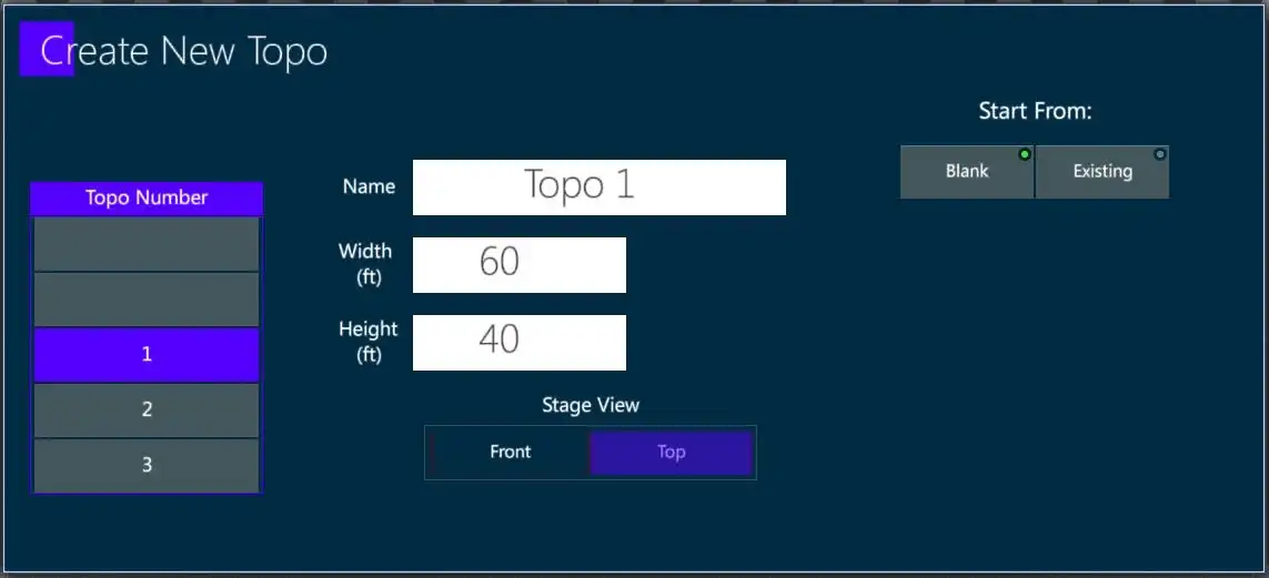
Select the desired Topo number, and give the Topo a unique name.
Enter the size of the Stage surface. The stage dimensions may be in be in Imperial or Metric. This default is set in the System Settings pop-up.
Select the stage point of view. The default is Top view.
Tap
aor press [ENTER] - This closes the pop-up, enters Topo {Edit} mode, and the grid will be displayed.
18.4 Adding fixtures
There are two ways to add fixtures to a Topo
Using keypad selection:
Press zoom option {FIT STAGE TO SCREEN} on the toolbar at the bottom of the Topo View to see the whole stage area.
Select the fixtures using the keypad or a group.
Tap {FROM EDITOR} on the toolbar at the bottom of the Topo View.
Selected fixtures will now appear in the top right section of the Topo.
initially, the fixtures will be selected (outlined in red), and can be dragged freely into place.
Double tap in a clear space on the TOPO to deselect.
If the {From Editor} key is selected with a long press (held for a few seconds) the fixtures may be directly dragged from the {From Editor} area. Only a maximum of 5 fixture icons will be shown but the whole selection will actually be there. Drag the fixtures to a location on the Topo view and release. The actual fixtures will now appear on the Topo surface. The reference point for dropping is the fixtures is the top left corner of the dragged fixture icons.
Using {ADD ELELMENTS} from the Topo menu:
Create the Topo
From the Topo menu tap {ADD ELEMENTS}
From the drop down, tap {SETS}
From the next drop down, select a fixture set - A list of the fixture in the set will drop down.
From the fixture list, select the fixtures to drag onto the Topo.
Press, hold and drag the fixtures onto the Topo surface.
Double tap in a blank area of the Topo to deselect the fixtures. Topo tools are provided to edit topo fixture placement and appearance.18.2. Topo Menu.
Add Sub Devices to the Topo View
Topo view supports the fixture layers, so sub-devices of a Fixture (for example 70, such as fixture 70.1 -> 70.7), can be added as independent objects.

18.5 Adding Pixel Maps
The pixel mapper creates a matrix of fixtures. The aspect ratio of the pixel map is controlled by the number of columns and rows that are created. Matrix fixtures may be selected by blocks using the rectangle lasso selection tool, or free-form path tool.
To create a new pixel mapper:
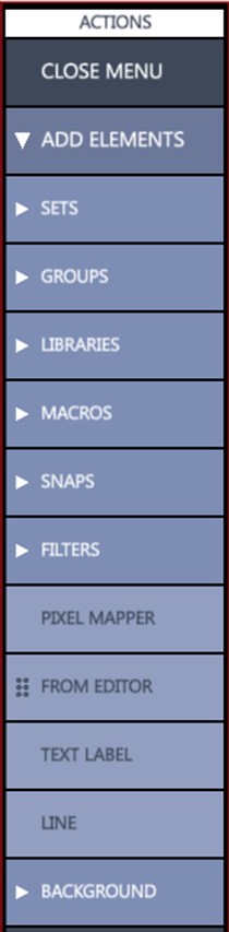
From the Topo Actions menu, tap {Add Elements}
From the {Add Elements} drop down, tap {Pixel Mapper} - The Create New Pixel Mapper pop-up will appear.
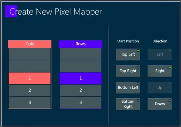
Fill in the number of columns and rows and set the start position and direction.
Press [Enter] or tap
to close the pop-up and create the blank pixel map.👉 Currently, the pixel map will appear in the top right corner and in some cases, a zoom out will be needed to find the pixel map and drag it back to the desired location..
Using the same methods for adding fixtures to the Topo, drag the fixtures into the pixel map matrix. Usually, this will be to the top left corner. 18.4. Adding fixtures to a Topo
Release the fixtures and they will populate the pixel map.
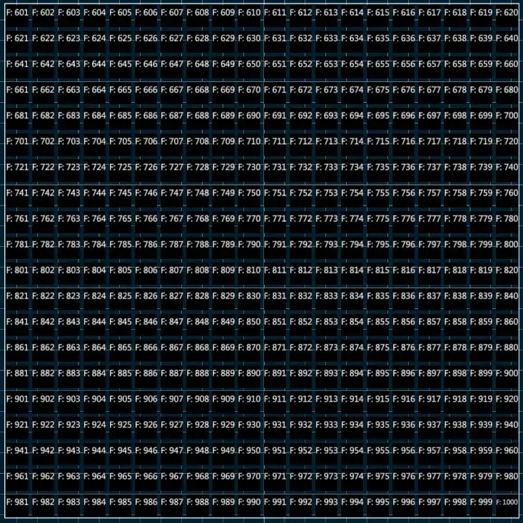
👉 The number of fixtures must not exceed the number of pixel mapper cells..
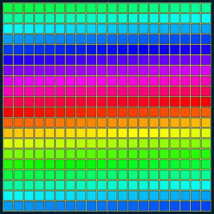
- The populated matrix in {Edit} Mode will display the fixture numbers in each cell. In {Live} Mode, the fixture’s color mix will be shown. CMY, RGB, and HSV color spaces are supported.
Multiple pixel mappers may be added to the same Topo along with other objects.
👉 The current Pixel Mapper is for the selection of fixtures and displaying of live output but future versions will add the ability to map content to individual pixel maps.
18.6 Adding Softkeys
There is an option to add softkeys of any type to the Topo with dragging and dropping items from the menu.
18.7 Adding Text Elements
Text labels:
From the Topo Actions menu, tap {Add Elements}
From the drop down, tap {Text Label} - The Create Label pop-up will appear.
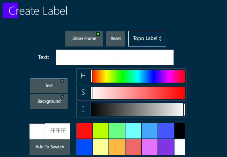
Close the pop-up and the test label will appear on the Topo surface.
Drag the label to the desired location.
Transpose tools may be used to size and rotate the label.
Backgrounds such as studio layouts and rig elements may be added to the Topo.
18.8 Adding Background Image
To add a Background to a Topo:
Prepare a USB stick with a JPEG, BMP, or PNG piece of content.
Insert the USB stick into one of the Vibe’s USB ports.
From the Topo Actions menu, tap {Add Elements}.
Tap {Add Background} - A browser pop-up will appear.
Select the USB stick and click on the desired content - Once imported, the content may be found in the default local directory on the hard-drive under D:
Tap {Load}, [Enter] or tap
to close the pop-up and place the content as a background to the Topo.To remove the background tap {Remove Background}
Topo background images can be edited in size and position.